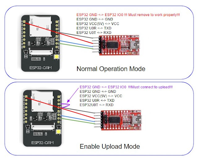
However, many people reported errors when powering the ESP32-CAM with 3.3V, so we always advise to power the ESP32-CAM through the 5V pin. You can power the ESP32-CAM through the 3.3V or 5V pins. The ESP32-CAM comes with three GND pins (colored in black color) and two power pins (colored with red color): 3.3V and 5V. You can download a PDF file with better resolution on this GitHub repository. The following figure shows the schematic diagram for the ESP32-CAM. The following image shows the pinout diagram for the ESP32-CAM AI-Thinker.

In this guide, we’ll take a look at the ESP32-CAM GPIOs and how to use them. The ESP32-CAM is a development board with an ESP32-S chip, an OV2640 camera, microSD card slot and several GPIOs to connect peripherals.


 0 kommentar(er)
